Models for the Overhead Projector
- Clutches, Transmission, Synchromesh, Automatic Transmission
Models for the Overhead Projector
|
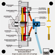
Order No. 115
- motion shown when pressure plate is lifted |
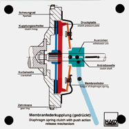
Order No. 116
- motion shown when the pressure plate is lifted |
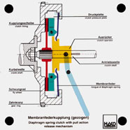
Order No. 117
- characteristics of a pulled clutch in motion |
|
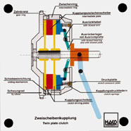
Order No. 207
- function of a double-disk clutch |
|
Order No. 293
- pressing the clutch pressure pin by means of the lever |
|
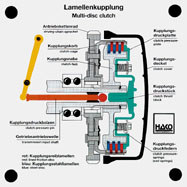
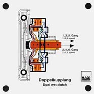
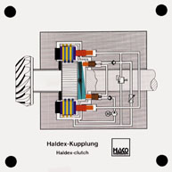
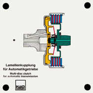
Order No. 470
- Function of a dual wet clutch with disks |
|
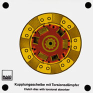
Order No. 447
- Purpose of the torsion-bar suspension |
|
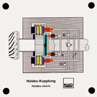
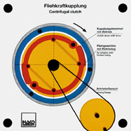
Order No. 429
It replaces the viscous clutch in four-wheel drive. As soon as a
difference in speed comes about between front and rear axle, the
swash plate begins to turn. In this, it operates the pump
plunger, which presses hydraulic oil into the plunger of the
friction disks. |
|
Order No. 295
- turning the driving crank sets the driving flange into motion
|
|
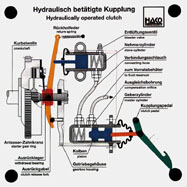
Order No. 279
- interaction of master cylinder and slave cylinder |
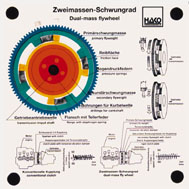
Order No. 275
- design of a dual-mass flywheel |
|
|
Order No. 469
- Rotation of the secondary flywheel mass against the primary
flywheel |
|
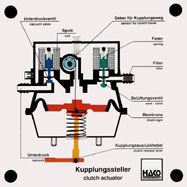
Order No. 324
- function of the solenoid valves |
|
Order No. 199
- this model facilitates the understanding of a modern car
transmission |
Order No. 201
"reverse gear" |
|
|
|
|
|
|
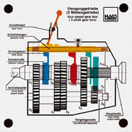
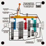
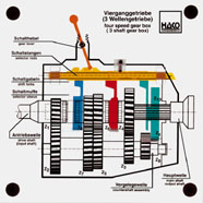
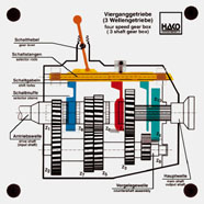
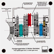
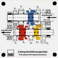
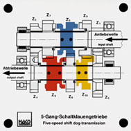
Order No. 202
- power distribution in a five-speed transmission |
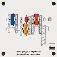
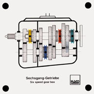
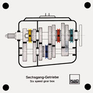
Order No. 466
- shifting the six forward gears by displacing the gearshift
sleeves |
|
|
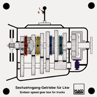
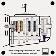
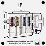
Order No. 438
The basic module comprises a gearbox with four gears. By adding
a front-mounted and a rear-mounted module, a sixteen-speed
gearbox results. With the help of the left-hand sleeve, the ... |
|
|
|
Order No. 433
This gearbox is ideal for demonstrating the power flow in the
individual gears. The shifting sleeves are distributed to both
main shafts. A fourth shifting sleeve was required for the
synchronised reverse gear. |
|
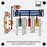
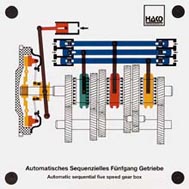
Order No. 467
- function of an automatic sequential transmission |
|
|
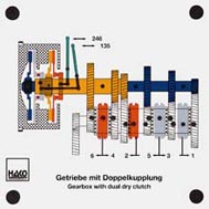
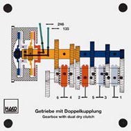
Order No. 465
- operation and function of both clutches |
|
|
Order No. 432
This new construction by the firm of GRETAG shows a mechanical
manual transmission with six forward gears and one reverse gear.
A gear selector drum driven by an electric motor operates the
shifting. |
|
|
|
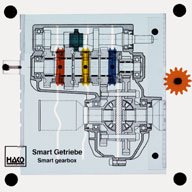
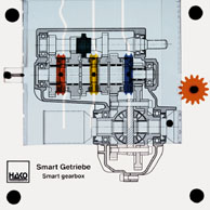
Order No. 270
- function of a draw-key transmission |
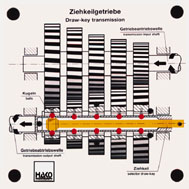
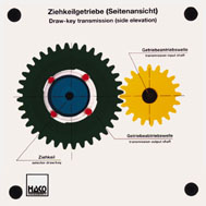
Order No. 278
(section of side view) |
|
|
Order No. 451
- Flow of force in the shift dog transmission |
|
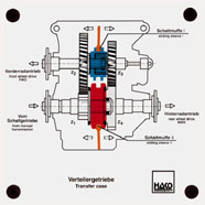
Order No. 203
- power distribution in a transfer case |
|
Order No. 144
-gearshift rod with gearshift fork in motion |
|
|
|
Order No. 439
- Movement of gearshift rod and gearshift fork |
|
|
|
Order No. 400
- moving the gearshift fork and sliding sleeve |
|
|
|
Order No. 186
"idle position" |
|
|
|
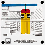
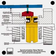
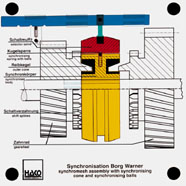
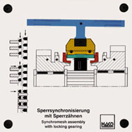
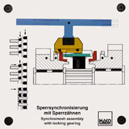
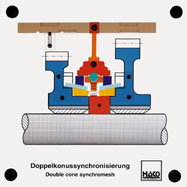
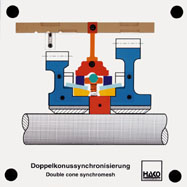
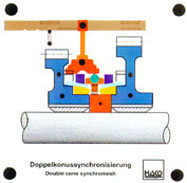
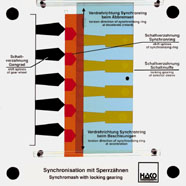
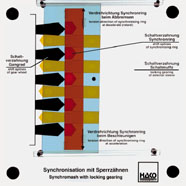
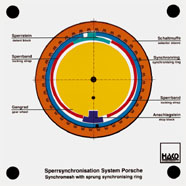
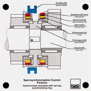
Order No. 164
- dragging of the split synchronizing ring |
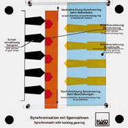
Order No. 204
- this longitudinal section of a locking synchronization
facilitates the understanding of model #164 |
|
|
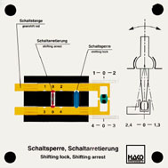
Order No. 371
The shifting arrest prevent 2 gears from being selected
simultaneously by locking the other gearshift rod.
Demonstration: that the simultaneous selection of two gears is
not possible. |
|
|
|
Order No. 430
Functions: |
|
|
|
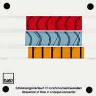
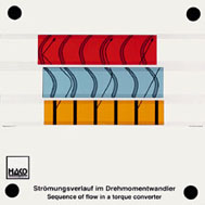
Order No. 462
The model shows the turbine wheel, the pump wheel and the stator
on one level. |
... favourable angle by the stator. There is an increase of the
engine torque. |
The stiffening force and thus also the torque reinforcement
becomes less. |
|
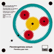
Order No. 239
- all transmission ratios of a simple planetary gear train can
be shown by driving by driving and locking different parts of
the model from the outside |
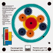
Order No. 240
Ravigneaux gear set |
Order No. 385
- Two simple planetary gear sets are combined to formed a
single set. The Simpson gear set has 2 ring gears, 2 planet
carriers and two connected sun wheels. Various gears (forwards
and reverse) can be selected. |
|
Order No. 215
Principles of an automatic transmission |
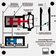
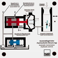
Order No. 227
- the model shows how pressure variations in the intake
manifold (i.e.load) act on the control piston via a diaphragm;
the control piston influences the shift points of the automatic
transmission |
|
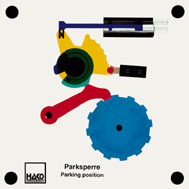
|
Order No. 372
If the selector lever of an automatic transmission is on "P",
the park position is engaged and prevents the vehicle from
rolling. |
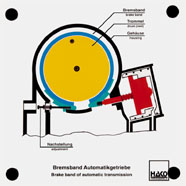
|
Order No. 373
Hydraulic clutches are necessary for shifting the planetary gear
train. Function of the ventilating system. Power flow: the
piston presses the discs. |
|
Order No. 179
automatic transmission |
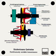
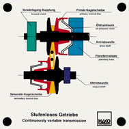
Order No. 384
The transfer of power from the primary conical disc to the
secondary conical disc is made by means of the sliding
articulated band. |
|
|
Order No. 229
The gear drive without backlash, mainly used for motor bikes,
has on one shaft a gear wheel with 49 teeth and another gear
wheel with 50 teeth. The two are axially preloaded against each
other. With every rotation, the gear wheel with 49 teeth is
turned one tooth farther than the gear wheel with 50 teeth. This
causes a gear drive without backlash.
|
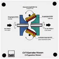
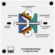
Order No. 448
Infinite transmission for rear-wheel driven cars, suitable up to
500 Nm. A roll is used for the force transmission. Pivoting the
roll alters the gear ratio infinitely.
|
|
|
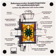
Order No. 269
with friction plates |
|