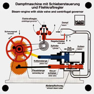
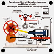
Models for the Overhead Projector
- Combustion Engines, Steam Engines, Stirling Engines, Engine Management,
Other
Models, Model Stand and Model Cabinet for OHP-Models
Models for the Overhead Projector
|
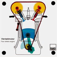
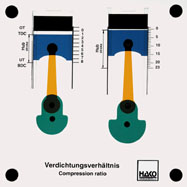
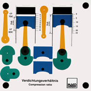
Order No. 101
- drive of the double overhead camshaft |
Order No. 255
- crankshaft drive, stroke of a piston |
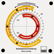
Order No. 417
- all the functions of a four-stroke engine can be shown with
valve overlap |
|
|
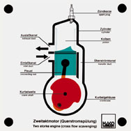
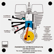
Order No. 102
- function of combustion chamber and crankcase |
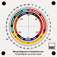
Order No. 193
- principle of a modern two stroke engine |
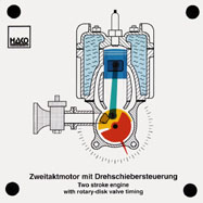
Order No. 398
- gas control in a two-stroke engine with rotary-disk valve |
|
|
Order No. 191
-
the OHV-engine is driven by means of a crankshaft, tappet and
rocker arm |
Order No. 287
- function of crankshaft drive |
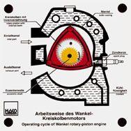
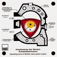
Order No. 238
- the bid and solid overhead model shows how a Wankel engine
works, especially the function of an eccentric shaft and gearing |
|
|
|
Order No. 301
The two engines are connected by gear wheels and are turning
simultaneously |
|
|
|
Order No. 283
- function of the piston and flywheel |
|
Order No. 289
- function of a rhomboid gear-set |
|
|
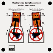
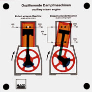
Order No. 319
the simplest form of a reciprocating engine is a steam engine
with oscillating cylinders. The model shows both the
single-acting and the double-acting engine. The mode of
operation of the engine and the control of steam inlet
... |
|
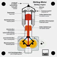
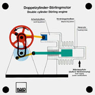
Order No. 304
- function of a double-cylinder Stirling engine |
|
|
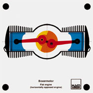
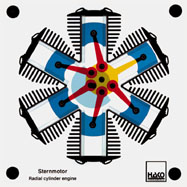
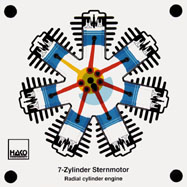
Order No. 104
- characteristics of a flat engine in motion |
Order No. 105
- arrangement of the cylinders |
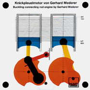
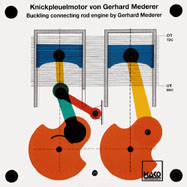
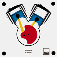
Order No. 103
- function of a the master connecting rod |
|
|
Order No. 420
- function of a radial engine according to the four-stroke
principle |
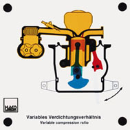
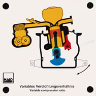
Order No. 457
(SVC engine) |
|
|
|
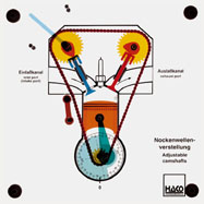
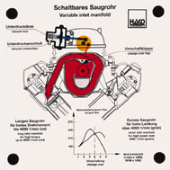
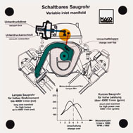
Order No. 395
- the opening and closing angle of the discharge and inlet
valves can be adjusted as required |
Order No. 399
Setting the various angles for: |
|
|
|
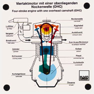
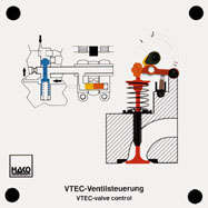
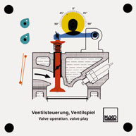
Order No. 187
all functions of a four stroke engine can be shown, incl. chain
tensioning. Inlet valve and exhaust valve openings can be read
in degrees. Valve opening and closing as well as valve
overlapping can be shown. The inlet cam can be advanced by means
of a lifting cam and power screw. |
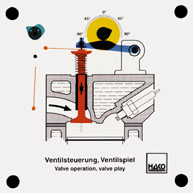
Order No. 235
Advancing the inlet camshaft by means of two sliding chain
tensioners, which can be moved to and from via magnetohydraulic
actuation. The exhaust camshaft is driven by the crankshaft. The
inlet camshaft is driven by the outlet camshaft via a chain. |
Order No. 419
- valve control in the lowest speed range with drag levers
released |
|
|
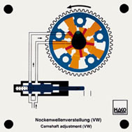
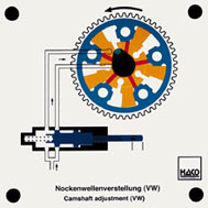
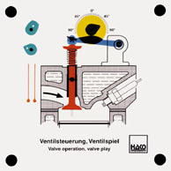
Order No. 463
In this, the adjustment of the inlet and the outlet camshaft is
done with the help of hydraulically operated vane adjuster. In
an outer rotor, an inner rotor is rotated hydraulically
clockwise or anti-clockwise and adjusts the camshaft in the
direction of early or late. |
The maximum adjustment angle is 52° crank angle with the inlet
camshaft and 22° with the outlet camshaft. |
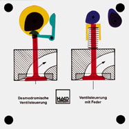
Order No. 130
- function of the desmotronic valve actuation (with cams to open
and close the valve) |
|
|
Order No. 435
Functions: |
|
|
|
|
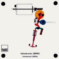
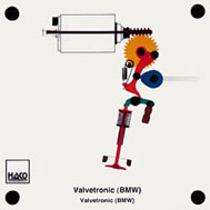
Order No. 460
Instead of a throttle valve, the differing valve stroke is used
in the Valvetronic to control the fresh gas. An eccentric shaft
is operated by the engine management via an electric motor, a
worm and a work wheel. |
The eccentric shaft controls an oscillating lever between the
cam shaft and the rocker arm, with the result that the cam of
the inlet camshaft opens the valve to differing extents (from
zero stroke up to maximum stroke). |
Fig. 1: Zero stroke (valve remains closed) |
|
|
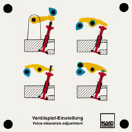
Order No. 390
It is possible to demonstrate 4 different ways of setting the
valve clearance, by rotating the adjusting screws on the rocker
arm or rocker lever, by inserting discs of varying thickness or
by means of an eccentric on the rocker arm. |
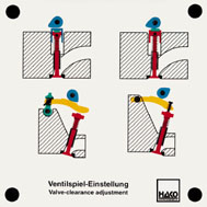
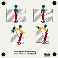
Order No. 391
It is possible to demonstrate 4 different ways of setting the
valve clearance. By inserting discs of varying thickness in or
under the bucket tappet. By rotating the adjusting screws on the
rocker arm and rocker lever. |
|
|
|
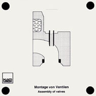
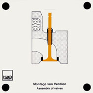
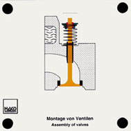
Order No. 464
The assembly of a valve into the
cylinder head can be demonstrated clearly: |
- Insertion of the valve shaft into the sleeve on the cylinder
head Pushing the valve shaft sealing on |
- Pushing the spring valve and the spring cap on Pushing the
spring valve over the spring cap Pushing the valve key into
the groove of the spring cap |
|
|
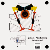
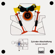
Order No. 434
The cylinder shutoff, a new development for the new Daimler Benz
S class, is switched on and off electro-hydraulically by the
control unit. In the lower load area, 4 cylinders are switched
off, in the upper load area there is a switch-over to 8
cylinders. The valves are operated in a locked state. If the
coupling pins ... |
|
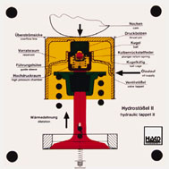
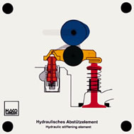
Order No. 131
- how the hydraulic valve tappet works under pressure and
release |
|
|
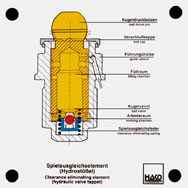
Order No. 268
This hydraulic tappet is designed as a bucket tappet and makes a
valve adjustment without clearance possible. Function of high
pressure chamber, ball valve, clearance-eliminating spring and
valve tappet can be shown. |
Order No. 459
The following can be shown: |
|
|
|
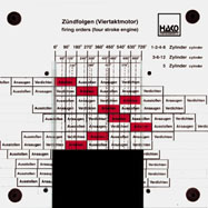
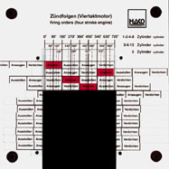
Order No. 145
- firing order of one- to twelve-cylinder engines |
Order No. 145 E |
||
|
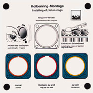
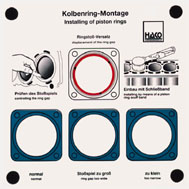
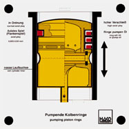
Order No. 250
- inserting three different piston rings shows an incorrect and
correct ring gap |
|
Order No. 211
- when moving the pistons to and from, you can see how the
piston rings slide up and down in the grooves if there is too
much clearance: Oil is pumped into the combustion chamber |
|
|
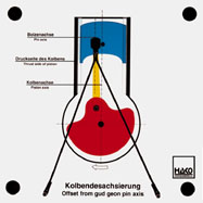
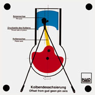
Order No. 146
- without offset: piston changes bearing surface after TDC |
|
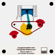
Order No. 189
- the two balance shafts of a four-cylinder inline engine
turn towards each other with double crankshaft RPM |
|
|
Order No. 276
Functions: |
|
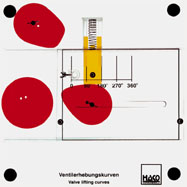
Order No. 196
The filling curves of three different cam shapes can be drawn
directly on a mobile slide by means of the three enclosed felt
pens (red, blue and green). |
|
|
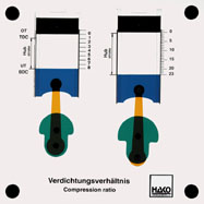
Order No. 337
Working out of the different capacities: |
|
|
|
|
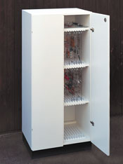
Order No. 1015
- for storing approx. 50 to 60 OH models (depending on
height), made of synthetic - laminated chipboard, lockable |
Order No. 1014
-
for storing 10 OH models made of veneered plywood |
||