|
|
|
The FORCES range of Hi-Tech Education equipment enables clear and comprehensive learning of STATICS and DYNAMICS covering a variety of theories and topics. An understanding of the way in which forces act and react, is fundamental when studying the application of loads on a variety of fixed structures and rotating machinery. The FORCES form a comprehensive range of equipment, from fixed beams through to rotating machines apparatus, equally suitable for demonstration and experimental work.
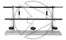
HFC1 Reactions of Beams ApparatusThis apparatus is designed for simple experiments and demonstrations on simply supported beams. Two spring balances act as supports and enable reactions to be read directly. Three movable load hangers allow loads to be put in a number of positions. |
 |
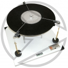
HFC2 Triangle of Forces ApparatusA bench mounted circular table with a central pin and 360º protractor has three pulleys on adjustable clamps round the edge. Conditions of equilibrium are obtained by centralising a small cord ring over the central pin with cords to load hangers where the loads and lines of action are variable. The triangle of forces in equilibrium can be constructed and the resultant of two known forces can be found. |
 |
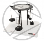
HFC3 Funicular Polygon and Forces ApparatusThis apparatus is a more comprehensive and versatile version of the HFC2. A simple but elegant demonstration of the conditions of equilibrium for three or more coplanar forces acting either at a point, on a circular disc or on a rectangular shape. |
 |
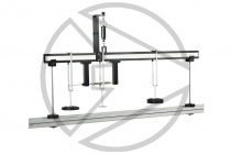
HFC4 Shearing Force ApparatusThis experiment demonstrates the nature of the internal forces and their dependence on the external system of forces for a simply supported beam. The experimental beam is in two parts, joined by a pair of ball bearing rollers running in flat vertical tracks. To develop the internal beam forces at the section an underslung tension spring is used to resist the bending moment, while an overhung spring balance provides the vertical shearing force. The shear force can then be directly read from the vertical spring balance. The beam is simply supported on end bearings and several weight hangers can be attached at any position on either side of the joint. |
 |
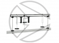
HFC5 Bending Moment ApparatusThis experiment demonstrates the nature of internal forces and their dependence on the external system of forces for a simply supported beam. The experimental beam is in two parts joined by a pair of ball bearings running in a profiled groove. An underslung spring balance provides a resisting moment, and also allows the section bending moment to be measured. When load is applied to the beams the spring balance is adjusted to bring the beam horizontal and the bending moment force recorded. Load is applied by the use of calibrated weights and three specially designed hangers which have a single point contact on the beam and can be positioned anywhere along the working length of the beam section. The beam is simply supported on end bearings. The apparatus is quick and easy to set-up on a bench top and takes up little space. It is a visual experiment and different loadings can be applied accurately and quickly. |
 |
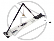
HFC7 Work Done by a Variable Force (Tangential Effort)This experiment is designed to reinforce the general principle that the work done, particularly by a variable force, can be determined simply by measuring the area under the graph of force and distance moved. |
 |
HFC8 Centre of Gravity ApparatusThe centre of gravity of a shape of uniform thickness can easily be found by this method. It provides a simple technique for complicated shapes, far quicker than by using calculus for example, although not producing an accurate answer to the handling of a yacht, the calculation of the moments caused by the wind and water acting at the 'centre of lateral area' of the sails and keel are still used as a starting point. A free standing backboard has a pin from which a selection of flat shapes can be hung. A simple pendulum suspended from the pin enables the line of action of the weight to be transferred to the lamina. The centre of gravity is the position on the shape where two or more such lines intersect. The shapes can be marked using a suitable pen and can be cleaned easily. |
 |
HFC9 Bell Crank LeverLever mechanisms of all shapes and sizes are very common parts of machines, particularly in hand operated devices. The bell crank lever offers the typical mechanical advantage of a lever, and in addition it turns the line of action of the effort through 90°. In most cases the cranked lever would be a casting with a bushed pivot at the corner. The experimental model has been built up from plastic to simulate the real thing. |
 |
HFC10 Fletchers TrolleyThis type of equipment has been used for many years to introduce students to accelerated linear motion, in particular the dependence of the acceleration on the net force causing the motion. Confirmation of Newton's second law of motion and the determination of gravitational acceleration are possible with this apparatus. This robust and traditional apparatus produces very accurate results. |
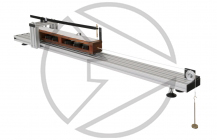 |
HFC11 Acceleration ApparatusThis type of equipment has been used for many years to introduce students to accelerated linear motion, in particular the dependence of the acceleration on the net force causing the motion. Confirmation of Newton's second law of motion and the determination of gravitational acceleration are possible with this apparatus. The trolley which carries five removable masses glides on two rails attached to the base. Electro-sensitive paper strip attached to the trolley passes through a spark generator which produces five impulses per second, enabling the trolley acceleration to be accurately determined. The weights which produce the accelerating force are hung directly onto the paper strip. All required equipment is supplied. Further rolls of electrosensitive paper are available. |
 |
HFC12 Three Wire SuspensionA free standing backboard provides supports for three tensile suspenders that meet at a ring carrying a load hanger. Spring balances measure the tension in each of the suspenders which are at about 30 and 45 degrees to the central vertical one. |
 |
HFC13 Rolling Disc on an Inclined PlaneThe moment of inertia of a rolling object is the rotary analogy of mass and governs the rotary acceleration. It can be determined in three ways; by rolling, oscillation or direct calculation. All should ideally give the same result but the student can be introduced to differences caused by different experimental techniques. |
 |
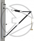
HFC14 Wall Jib CraneThis apparatus teaches students about the confluence of the four forces at the end of the wall jib crane and clearly illustrates the application of a triangle of forces. This wall mounted self-contained jib crane has spring balances built into its two members. After loading the member lengths can be adjusted to their no-load lengths. The experiment allows the student to determine the experimental values of the forces in the principal parts of the jib crane, study the effect of altering the length of the tie to change the geometry and to compare the results with the forces obtained from graphical solutions using a polygon or a triangle of forces. The jib out-hangs and the crane cable inclination can be readily changed. A set of calibrated weights and load hangers are supplied. |
 |
HFC16 Tension CoefficientsThe apparatus consists of a jib restrained by two chain ties making a triangulated three dimensional structure. The jib and both ties are fitted with spring balances so that the internal forces can be measured. |
 |
HFC17 Basic Roof TrussThe basic roof truss consists of two rafters or struts and a restraining tie. Both rafters are pivoted at their apex. The other end of one of the rafters is pivoted to a free standing base, whilst the remaining rafter end runs on ball bearings along a track. |
 |
HFC19 Toggle Joint ApparatusThis apparatus is designed to evaluate forces within a toggle mechanism. Load is applied to the two pairs of links by a hanger suspended from their connecting pivot. One end of the link is pivoted to the base, while the other end is able to move sideways on low friction ball bearing wheels. The moving links are restrained by a horizontal spring balance, which measures the horizontal reaction directly. The angle of the toggle can be varied and adjustment is provided for returning the geometry to its original unloaded state before taking measurements. There are many ways in which the forces can be determined theoretically. The instruction sheet provided with the apparatus takes the opportunity to introduce the use of velocity diagrams to solve essentially static problems by considering virtual motion. |
 |
HFC20 Simple Moment ApparatusThis equipment provides a simple easy to understand experiment on the equilibrium of moments. Several loads can be put on the beam at various positions. These will make the beam rotate. The student has to determine the moment necessary to overcome this rotation and keep the beam level. |
 |
HFC21 Centrifugal Force ApparatusThis apparatus is used to verify that centrifugal force varies with the square of the speed, the rotating mass, and the radius of gyration. The bench top mounted unit houses a speed-controlled motor, which carries a horizontal boom assembly. This assembly rotates up to 350rpm and onto which sliding weights are fitted and adjusted. The weights are attached to centrifugal rods, which move outwards during rotation and through crank levers apply a force to an integral load cell. The speed of rotation of the boom is displayed on the front panel along with the centrifugal force reading. A unique feature is that all three variables can be set and the centrifugal force directly read from the digital force display. Six masses are supplied along with all the necessary tools, spares and accessories. A protective dome covers all rotating parts giving protection to the end user. |
 |
HFC22 Rubber in Shear ApparatusRubber blocks in shear force are often used on engine and in equipment mounting to isolate vibrations. They do this by absorbing shock energy by deforming. This deformation leads to a decrease in cross-section as the block lengthens, an effect described by Poisson's Ratio. After this experiment, students will understand the behaviour of a very flexible material such as rubber. Rubber is interesting in that the lay person regards it as an 'elastic' material. In engineering terms it is not as 'elastic' as steel and often exhibits a high degree of hysteresis. |
 |
HFC25 Conservation of Angular MomentumConservation of linear momentum is well understood and often demonstrated to students. Equally important is the conservation of angular momentum. It is not easy to do meaningful experiments on this, but a highly visual demonstration of almost dramatic impact is the effect of reducing the radius of a rotating mass. This is often seen in an ice skater performing a pirouette. First they spin round on an axis corresponding to their body, arms outstretched. When they raise their arms above their head, the increase in spin in considerable. Rather than go to an ice rink, students can perform this experiments in the laboratory using the HFC25. |
 |
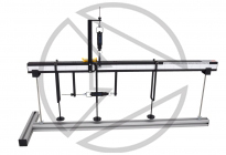
HFC26 Apparatus for Statics Experiments
The unit allows the fundamentals of Statics, such as equilibrium, force resolution, the principles of levers, and similar issues to be clearly demonstrated. The base unit is a freestanding board. All the parts necessary for the experiment can be quickly attached to the board straps and perimeter grooves on the edge of the board. Linear scales around the perimeter of the board allow for accurate measuring. Two large board straps allow the mounting of the individual experiment components. Each strap has equispaced threaded holes to allow mounting positions to be varied widely. Two ball bearings facilitate low friction torque experiments. All forces measured using analogue spring balances. The board can be written on with the use of the non-permanent pens. |
 |
HFC29 Coriolis Force ApparatusThis bench top unit gives excellent visual demonstration to the Coriolis Force on a jet of water. A horizontal boom sits on top of the main base unit and rotates in a horizontal plane. Attached to the boom is a water tank which projects a jet of water into the tank towards the centre of rotation of the boom. An electronically controlled motor rotates the boom at different rotational speeds. As the speed of boom rotation is changed, the jet of water deflects under the Coriolis affect (force). The amount of deflection can be seen on increments on the water tank. The speed of rotation of the boom is digitally displayed and controlled using the front panel mounted knob. The jet motor is operated using batteries supplied. A charger for the batteries is supplied also. All rotating components are protected within a clear safety dome. |
 |
HFC31 Combined Shear Force and Bending Moment apparatusThis compact bench top unit allows the observation and analysis of both Shear Force and Bending Moment within one unit. A rigid, aluminium beam is cut into two unequal lengths. Each part of the beam is then simply supported on vertical supports. Each support can be moved along the beam section length creating varied support positions. At the ‘cut’ section, a bearing allows for both vertical movement (shear) and rotation (bending) to occur. The Shear Force is measured using a vertical spring balance and the bending moment is measured using the horizontal spring balance. Special load hangers are provided that can be positioned accurately along the beams length by using the graduated scales attached to the side of the beams. The smooth design of the beam sections allows a wide variety of unrestricted load positions to be used along the beam lengths. |
 |
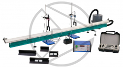
HFC33 Conservation of Linear MomentumThe HFC33 apparatus consists of a long precision air track manufactured from sturdy lightweight extrusion. A blower forces air through the extrusion and miniature holes running along its length. This creates a near frictionless ‘cushion’ of air onto which two trolleys can me moved which is crucial in preserving momentum in the Conservation of Momentum theory. The trolleys can be set onto each other in different modes. The trolleys can accept additional masses onto them to vary the experimental parameters. The trolleys are projected along the air track by means of a catapult device with buffers installed to stop the trolleys if necessary. Light gates on the track monitor the timing of each trolley and a linear scale allows the distance to be recorded and the timing gate positions to be accurately set. The apparatus can also teach kinetic and potential energy, velocity, acceleration and force. |
 |
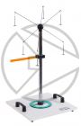
HFC34 Torque Vector ApparatusThe HFC34 investigates plane and spatial equilibrium of moments and vector addition. A table top base plate, with integral feet, supports a vertical pillar. The vertical pillar passes air through itself to the top. A small ball is rested at the top of the pillar and when air flows a small cushion of air is created for the ball to sit on. This creates a friction free bearing. The air flow is created using manual operation of a hand pump. The ball has six perpendicular rods protruding from its surface. Onto the ends of these rods hang load hangers and weights. The weights create varying moments and equilibrium positions.The six rods alsoallow up to six forces to be observed simultaneously. The length and angularposition of each rod is measured using the integral linear scale and protractor supplied. |
 |
HFC35 Rotational Apparatus
The HFC35 investigates rotational dynamics. A table top base plate, with integral feet, supports a rotating base plate. The base plate has a stepped pulley with three varying diameters onto which a cord can be wrapped. The free end of the cord attaches to a load hanger via a pulley. The rotating plate can be accelerated by adding weights to the load hanger. Attachments to the rotating plate include a hollow cylinder and rectangular bar, which varies the mass of the initial rotating plate. The rotating plate speed is captured using a sensor. The sensor points towards a black and white strip on the perimeter of the large rotating disc and the sensor picks up the different colours in order to monitor the speed. Data Acquisition Software supplied captures the key experimental parameters. |
 |
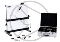
HFC38 Work Done by a Variable Force
This experiment is designed to reinforce the general principle that the work done, particularly by a variable force, can be determined by measuring the area under the graph of force against distance moved. On one side of the board a suspension cord carrying a loaded trolley at mid span is tensioned by passing the cord over a pulley at one end and down to a weight hanger. As the vertical effort is increased, the tensioned cord will move to a new equilibrium position lifting the loaded trolley. Heights of the load and effort are measured relative to the base. On the other side of the board a pivoted arm carrying a load hanger at its end is restrained by a spring balance at right angles to the arm. The angular position of the arm is indicated by a protractor scale attached to the back board. The effort is the force needed to hold the weighted arm at a particular angle. This can be repeated for several different weights. The back board is bench mounting. |
 |