|
|

|
The THEORY of MACHINES range of Hi-Tech Education equipment enables clear and comprehensive learning of and topics. An understanding of the way in which forces act and react, is fundamental when studying the application of loads on a variety of fixed structures and rotating machinery. The THEORY of MACHINES form a comprehensive range of equipment, equally suitable for demonstration and experimental work.
All the THEORY of MACHINES hardware operates in a standalone mode, with a large number being supplied with Data Acquisition Software.
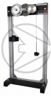
HTM1 Wheel and AxleWall mounted apparatus for investigating the mechanics of a simple wheel and axle machine. Students are able to obtain equations for the relationship between load and effort, and hence obtain a value for the limiting efficiency of the machine. Velocity ratios can be calculated along with understanding the effect on effort, friction and efficiency with increased load. |
 |
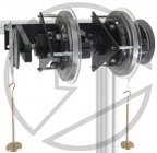
HTM2 Wheel and Differential AxleThrough the use of a wheel and stepped differential axle, students can determine the velocity ratio and comparison with calculated values for simple wheel and differential axle machine. |
 |
HTM3 Worm and Wheel (30 : 1 ratio)Wall mounted apparatus for analysis of the efficiency, velocity ratio and mechanical advantage of an industry standard worm and wheel pair |
 |
HTM4 Screw JackStudents determine the velocity ratio and compare this with calculated value. They can also determine the variation with load of effort, friction, efficiency and limiting efficiency of the machine. |
 |
HTM7 Gear Tooth FormThe gear form apparatus is designed to show and describe how gear teeth are defined and how basic gears work. It also explains the form of an involute curve and how this is used to create a gear tooth profile. |
 |
HTM8 Cam AnalysisThis compact bench mounted self contained apparatus enables the observation of the rise and fall of various cams and followers supplied. |
 |
HTM9 Simple FlywheelWall mounted apparatus to allow students to verify the second law of motion applied to a flywheel i.e. the relationship between torque and angular acceleration. Students can compare experimental and calculated moments of inertia of a disc as well as study the energy transformations. |
 |
HTM11 Spur Gear Lifting MachineThe floor or bench mounted apparatus assists in determining the mechanical advantage, velocity ratio, efficiency and limiting efficiency of a single or double gear train. |
 |
HTM13 Double Epicyclic Gear TrainWall mounted apparatus for the calculation and experimental observation of the angular velocity ratios within an epicyclic gear train. Students can also obtain the torque ratios and efficiencies of the gear train also. |
 |
HTM15 Model GyroscopeTo demonstrate visual precession and stability of a model gyroscope, and to assess the effect of direction of spin and speed of rotation. It will also allow the study of energy transformations and to demonstrate that a flywheel can be used to store energy. |
 |
HTM17 Crank and Connecting RodApparatus to show the relationship between crank shaft rotation and piston displacement for a fixed "cylinder". The stroke of the connecting rod and hence piston can be adjusted by securing its end to the different fixing points on the radius of the crankshaft. |
 |
HTM18 Oscillating CylinderApparatus to determine the relationship between crank angle and piston stroke, the effect of changing crank radius and evaluates the relationship between angular and linear speeds and accelerations. |
 |
HTM19 Hooke’s CouplingApparatus that allows the investigation into the relative angular displacements of shafts at opposite ends of a Hooke's coupling and observes the effect of changing the angles between the axes of the coupling and the interconnecting rod. |
 |
HTM20 Ackermann SteeringThis apparatus consists of a complete model Ackerman linkage mounted on a flat board. It is ideal for demonstration or experimental work and is an aid to understanding the design principles involved within a steering system. |
 |
HTM21 Castor, Camber, King Pin InclinationThis apparatus represents a scale model of the wishbone and king pin arrangement of a front wheel suspension complete with a wheel on an adjustable stub axle. The king pin assembly includes a steering link to demonstrate how a real car works. |
 |
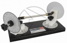
HTM22 Relationship between Angular and Linear SpeedsA stepped shaft with three diameters is carried in a bracket which then allows the comparison of the angular rotation of a shaft and the tangential speed at the circumference. |
 |
HTM23 Gear Train DemonstratorBench top unit to clearly demonstrate the functionality of gear trains, pulleys and belts. Based around a bench top unit, students can quickly assemble single and compound gear trains, pulley and belt arrangements. Theory and analysis behind the key elements of the apparatus function is supplied. |
 |
HTM24 Universal Drive ModuleThis compact bench top unit is constructed around a motor that is used for driving a variety of customer apparatus. The apparatus allows speed, torque and power to be monitored and calculated. |
 |
HTM25 Gear Train ApparatusUnderstanding the basics of gear trains is important. This apparatus ensures this is done in a simple, visual and durable way. Small, compact and self contained bench top unit for introducing students to gear trains and epicyclic gears. |
 |
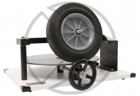
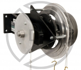
HTM26 Winch ApparatusThis industrial winch allows students to determine the efficiency, velocity ratio, characteristics of the winch under increased load and the safety elements of the winch. |
 |
HTM28 Crank MechanismCompact model and visual apparatus of a crank mechanism, with crank shaft, con rod and piston. This wall mounted apparatus is used by students to observe and record the crank motion and forces involved with a simple engine mechanism. |
 |
HTM34 Gearbox ApparatusThis apparatus represents a sliding mesh gearbox, with clear visible gears to aid the students understanding of the principles involved. |
 |
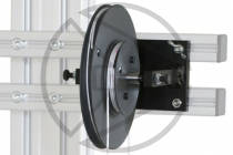
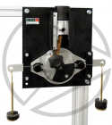
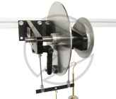
HTM38 Disc Brake ApparatusTo carry out experiments to investigate the relationship between the normal force acting on the brake pads, the effective radius of the brake pads and the braking torque. |
 |
HTM66 Static and Dynamic Balancing vibrationA self-contained bench top unit for the analysis of static and dynamic balancing of masses on shafts. Students learn about static and dynamic balancing, force polygons, couple polygons and vectors. |
 |
HTM67 Whirling of ShaftsTo be a bench top, self contained apparatus for the demonstration of whirling speeds of flexible shafts of different lengths and diameters. |
 |
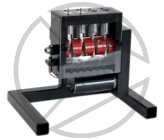
HTM68 Balancing of Reciprocating MassesSturdy bench mounted model four-cylinder engine to study the effect of oscillating masses on the vibration behaviour of the machine. Students also investigate different crank arrangements and effect of a weight added to one or more pistons. |
 |
HTM69 Geared SystemThe HTM69 apparatus consists of a 3-stage spur gear unit with 4 shafts. Each shaft has a pair of gears attached (spur and pinion) which mesh with the next shaft gear set. Each stage can be detached by the simple use of fixing pins. To change the inertia of the rotating gears and shafts, additional masses are supplied. The Digital Display Interface records the speed and can be used to generate speed-time diagrams from which the angular acceleration can read. Data acquisition software is supplied for further data analysis and manipulation. Unwinding of the gears and weights is prevented by a safety catch. A hand brake creates gentle braking whilst a transparent protective cover prevents contact with the internal rotating parts. |
 |
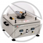
HTM70 GyroscopeThis bench top apparatus studies the moments generated by the gyroscopic effect. A vertical precession motor drives a gyroscopic yoke in a horizontal plane. Within the yoke is a horizontal spin motor and gyroscopic flywheel. The spin axis has a stationary shaft onto which is mounted a sliding balance mass to help vary the gyroscopic moment. The speeds of both motors are independently controlled and displayed on the front panel of the base unit. The gyroscopic yoke is able to displace through small angles between two fixed pins. A transparent safety guard provides protection against the rotating parts. |
 |
HTM71 Governors ApparatusBench top apparatus to demonstrate the principle of operation of various centrifugal governors of Porter, Proell and Hartnell form. A speed controlled vertical shaft allows the governors to rotate in a vertical plane, with the speed of rotation displayed on a digital meter. Students can observe the effect of speed of rotation, lifted mass, rotating mass and geometry on the lift of the governor. From this the sensitivity of each governor can be recorded and observed. The sleeve mass of the Porter and Proell governor can be adjusted by the weights set supplied. The Hartnell governor sleeve can be adjusted by the different springs supplied. Students plot graphs and record lengths, masses and distances for each governor. A transparent safety guard provides protection against the rotating parts. |
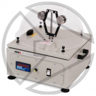 |
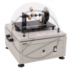
HTM72 Cam AnalysisBench top apparatus to demonstrate the dynamic investigation of cam and follower mechanisms, as used in motors for actuation of the valves. The cam mechanism consists of 4 interchangeable cams and 2 different cam followers. A mass and spring are used to simulate the valve. To demonstrate "valve bounce", the spring rate, lifted mass, spring compression and speed are all adjustable. A set of springs and added masses are supplied. Each cam is easily interchanged. A Data Acquisition Interface with software is supplied to allow the rise and fall of the cam to be monitored. Valve bounce can be easily observed using the interface and software. All rotating parts are contained within a transparent safety guard. |
 |
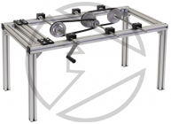
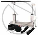
HTM73 Gear Assembly Unit Combined DrivesBased around a rigid, sturdy frame a variety of drive arrangements can easily be interchanged and fixed into position. Bearing blocks ensure excellent, repeatable alignment of the drives along with smooth running. The drive arrangements include dual belt drive, chain drive with tensioner, spur gear train, dual spur gear, compound bevel gear and spur gear, compound worm / wheel gear and bevel gear, rack and pinion with a spur gear drive. A cranked handle operates the drives giving more control and feel for each drive arrangement. The layout of the drives gives an excellent visual indication of motion, direction, velocity, and mechanical action. |
 |
HTM77 Slotted LinkThis disc has a pointer so that the input angle can be exactly read on the integrated angle measuring scale. The crank pin can be set at different radii on the disc. The slider crank is attached to the crank pin on one side. On the other side the pin is mounted in straight guide that is fitted with a ruler to allow the output stroke to be read off with precision. |
 |
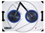
HTM78 Four Bar ChainA sturdy bench top base, with mounting feet and carry handles, incorporates a disc mounted on ball bearings as a crank. The disc has a protractors angle scale so that the rotational angle can be accurately viewed and measured. The crank pin connecting the crank to the disc can be set at different radii on the disc. The connecting rod and the oscillating lever are connected together in different lengths using quick-fit bolts. |
 |
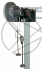
HTM79 Inertia in Rotational MotionA sturdy based plate contains two vertical rods. One supports a pulley wheel over which runs the test cord, whilst the other vertical rod supports a bearing housing onto which all the test bodies are easily attached. To minimize friction, the bearing housing contains two precision bearings. Three test bodies are supplied: solid cylinder, hollow cylinder and rectangular bar. All mount quickly and easily to the bearing housing. Clamp on weights are provided which easily and quickly attach to the rectangular bar using plastic screws. The radius of gyration of the clamp on weights can be easily adjusted and measured. |
 |
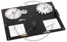
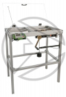
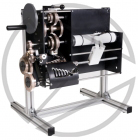
HTM80 Lathe Gear DemonstratorA sturdy vertical frame holds a number of gears and shafts for demonstrating the operation of a lathe and its associated gearing. The gearing comprises of primary, change, tumbler and quick change gear units, all mounted on precision shafts running in bearings. The shafts and gears can be rotated freely and easily by using the integral crank handle and by manual input. The lathe tool output is simulated using a pen and plotter arrangement. The pen moves in the directions dictated by the lathe gearing and operator and maps out the movements onto a roll of paper. |
 |
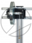
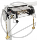
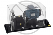
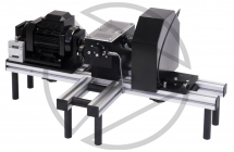
HTM81 Gear Efficiency ApparatusA sturdy frame has a motor mounted along with either a worm or spur gearbox. The input and output power is monitored for determining the gear efficiency of a worm and spur gearbox. The grooves within the frame allow for fine adjustment and easy removal of each gearbox and control component. The motor mounts inside a swinging cradle, which is connected directly to a load cell, allowing the motor torque to be monitored. Each gearbox is attached in turn along with a braking system to load the gearboxes and change the experiment parameters. The motor is accurately speed controlled and along with torque and current displayed on the control box displays. |
 |
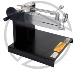
HTM82 Screw TesterA sturdy base plate holds a slotted steel beam horizontally. The two part beam allows easy deflection when a standard bolt is tightened into it. The deflection of the two parts of the beam is monitored using a deflection indicator attached at the end of the beam. This deflection is directly related to the tension force generated in the bolt. To reduce the friction a precision thrust bearing is used which the head of the bolt runs on. The torque is applied to the bolt using a torque wrench, lever arm and screw jack mechanism. The screw jack ensures precise loading of the bolt, and the movement of this mechanism is monitored using a second deflection indicator. |
 |
HTM96 Simple Bearing HousingHTM96 Simple Bearing Housing |
 |
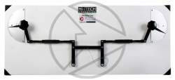
HTM97 Motor Driven Scotch YokeThe principal components are made from anodised aluminium, pivoted with hollow rivets, and mounted on a white board for contrast and visibility. The driven components can be operated by hand or alternatively operated using the motor and speed control supplied. A simple and easy interconnection is utilised to swap between motor driven or hand operated. A clear safety guard is used when motor driven. |
 |
HTM98 Single Epicyclic Gear TrainThe gear train consists of a sun gear in the centre, three planet gears, a planet linkage and an internal or ring gear. The sun gear, ring gear and planet carrier all rotate about the same axis. The planet gears are mounted on shafts that turn in planet carrier and meshes with both the sun gear and the ring gear. Pulleys fitted with protractors are attached to the input and output shaft so that torque and velocity ratios may be determined. Torques can be applied to the shaft by adding weights on cords wrapped on the pulleys. By Locking pins are used to holding different parts of the apparatus in position. This gives the user different options on gear ratios that can be applied between the input and output shafts. |
 |
HAC14 Vertical StandThis accessory allows the safe and secure attachment of a large variety of wall mounted experiments from the Hi-Tech Education range of teaching products. |
 |